Idle Settings
Idle settings
Idle Control mode
Open Loop disables the Closed Loop Idle strategy for the IACV/ETB. Open Loop + Closed Loop enables the Closed Loop Idle Strategy for the IACV/ETB. Closed Loop Idle Ignition Timing can be enabled separately.
Idle Detection Thresholds
The below settings are utilized to prevent the closed loop idle air strategy from engaging when it is not desired.
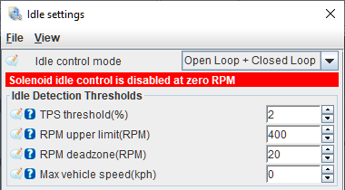
TPS Threshold
The TPS value must be below this % before the idle state can be entered. When using an Electronic Throttle Body (ETB) this references the Accelerator Pedal Position sensor instead.
RPM upper limit
The engine speed must be at or below the idle target RPM plus this value before the idle state can be entered. For example, if the idle target RPM is 750 RPM and this value is set to 200, the engine speed must be at or below 950 RPM before closed loop idle can be entered.
RPM deadzone
When the engine speed is within this many RPM of the target idle RPM, the closed loop idle algorithm is disabled. This is to prevent unwanted oscillation around the target.
Max vehicle speed
The VSS must be at or below this speed before the idle state can be entered. Setting this to 0 disables this check and enables closed loop idle air control at any speed.
Open Loop Idle
Open loop base position
Used to set the base value for idle control. Typically set to provide an idle slightly above the target RPM when the engine is fully warmed up. Log variable is Idle: Open loop.
A/C adder
This percentage is added to the open loop base position when the A/C is active, used to compensate for the additional load the A/C compressor puts on the engine.
A/C target adder
Added to the closed loop Idle Target RPM when the A/C is active, can be used to ensure the compressor is spinning quickly enough for desired cooling.
Fan #1 adder, Fan #2 adder
Added to the open loop base position when the fans are activated. May compensate for the additional electrical load on the alternator.
Extra idle air if throttle pressed
Closed Loop Idle
The closed loop idle air strategy can utilize all three terms (Proportional, Integral, Derivative) to provide accurate control of the IACV or ETB position and achieve a stable target idle. The 3 terms are calculated, added up and then limited by the Min or Max values to arrive at the final Idle: Closed Loop output. The error (difference between the Idle Target RPM and actual RPM) is written on the variable idleStatus_Error.
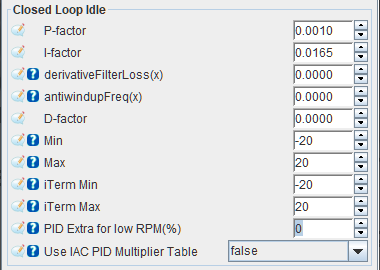
P-factor
Sets the Proportional gain of the closed loop idle air strategy, used to generate the P Term. Unity gain results in a P term output equal to the error, (Idle Target RPM - actual RPM). Log variable is idleStatus_pTerm.
For example, an instantaneous error of 100 RPM with a P-factor gain of 0.5 would result in a P term output of 50%.
I-factor
Sets the Integral gain of the closed loop idle air strategy, used to generate the I Term. Unity gain results in an I term output equal to the error/second, (Idle Target RPM - actual RPM)/sec. Log variable is idleStatus_iTerm.
For example, a consistent error of 100 RPM with an I-factor gain of 0.01 would result in an I term output that increases by 1% every second.
derivativeFilterLoss
antiwindupFreq
Used to limit the Integral term (iTerm) windup when the closed loop idle air strategy output is being limited by the min/max duty cycle limit. Once the Integral term has been calculated and limited if appropriate (iTerm Min, iTerm Max), if the output of the closed loop idle air PID controller exceeds the overall PID Min or Max settings, the Integral term is further limited to prevent integral windup. As long as the output of the closed loop idle air strategy exceeds the limits set by Min or Max, the I term is continuously modified.
iTerm += dTime(sec) * antiwindupFreq * (ClosedLoopLimitedOutput - ClosedLoopOutput)
dTime is the delta time since the closed loop idle air PID controller last ran.
Keep in mind that the Integral term is updated every time the closed loop idle air PID control strategy runs and will continue to be modified based on the error and I-factor gain. Additionally, if ClosedLoopLimitedOutput equals ClosedLoopOutput, antiwindupFreq has no effect.
D-factor
Sets the Derivative gain of the closed loop idle air strategy, used to generate the D Term. Log variable is idleStatus_dTerm.
Min, Max
Sets the minimum and maximum duty cycle modifier that can be commanded by the closed loop idle air strategy. The P, I and D terms are added up then limited based on the Min and Max values to give the Idle: Closed loop output. This is then added to the open loop base position to result in the final output, Idle: Position.
iTerm Min, iTerm Max
Sets the minimum and maximum duty cycle modifier for the I-factor specifically.
PID Extra for low RPM
Use IAC PID Multiplier Table
Extra Idle Features
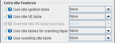
Use idle ignition table
Setting this to true activates a separate ignition timing table (2D) for idle conditions; this can help idle stability by using ignition retard and advance either side of the desired idle speed. false disables the timing table.
Use idle VE table
Setting this to true activates a separate fuel table (3D) for idle, which allows fine tuning of the idle fuelling. false disables the VE table.
See the Idle VE Table page for more detail about idle-specific VE settings.
Override idle VE table load axis
Override the Y axis (load) value used for only the Idle VE table. Setting this to none disables the override.
Use idle tables for cranking taper
This enables the separate ignition timing and VE tables not only for idle conditions, also during the postcranking-to-idle taper transition. See Cranking > Cranking settings > Idle air valve > After cranking IAC taper duration.
Use coasting idle table
Override the IAC position during overrun conditions. This can be used to help reduce engine braking, for large engines in light weight cars or for engines that have trouble returning to idle.
Idle Target RPM
Found under Idle > Target RPM.
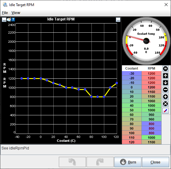
Defines the target idle RPM used by the main Closed Loop Idle air strategy as well as Closed Loop Idle Ignition Timing. Log variable is Idle: Target RPM.
Warmup idle multiplier/CLT multiplier
Found under Idle > CLT Multiplier.
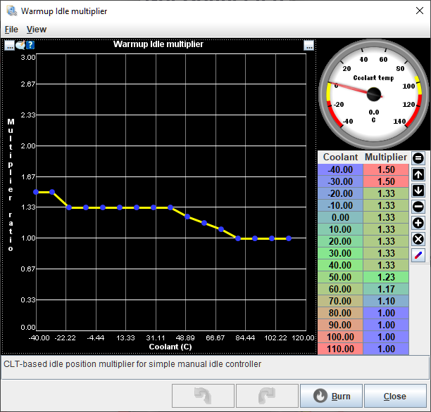
The open loop base position value is multiplied by the value in this table. For example, if the open loop base position value was 30% and the multiplier was 1.50 at 0 degC, the commanded base position at 0 degC would be 45%. A multiplier of 1 would simply output the open loop base position value.
Closed-loop idle timing
Found under Idle > Closed-loop idle timing.
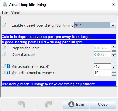
Enable closed loop idle ignition timing
True enables the closed loop idle ignition timing loop strategy, false disables it.
Proportional gain
Unity gain (1.0000) results in 1 deg CKA for every 1 RPM of error between actual engine speed and target engine speed. For example, a gain of 0.1000 results in 1 deg CKA for every 10 RPM of error. If the engine speed is 100 RPM below the Idle target RPM the resulting output would be +10 deg CKA (advance).
Derivative gain
Min Adjustment, Max Adjustment
Limits the minimum and maximum amount of timing adjustment output by the closed loop idle ignition timing strategy. Keep these values to the minimum required to avoid excessive spark advance or retard at idle speeds.
IAC PID Multiplier
Only enabled when Use IAC PID Multiplier Table is set to true.
Coasting IAC Position
Found under Idle > Coasting IAC Position.
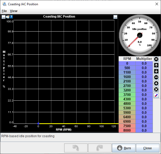
Only enabled when Use coasting Idle Table is set to true. 2D Table. When the engine is in the coasting phase, the IAC base position is set to the value defined by this table. This table is not used if the engine is not in the coasting phase and the open loop base position will be used instead.
Despite the multiplier label in the table, this table sets the IAC position in % duty cycle just like open loop base position - this is not a multiplier applied to the base position.
Idle VE
Only enabled when Use idle VE table is set to true. 3D table. Used in place of the regular VE table when idle is active, or during the cranking taper if Use idle tables for cranking taper is set to true.
See the Idle VE Table page for more detail about idle-specific VE settings.
Idle Ignition Advance
Found under Idle > Ignition Advance.
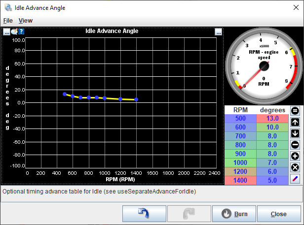
Only enabled when Use idle ignition table is set to true. 2D table (curve). The values in this table are used in place of the regular ignition curve when idle is active, or during the cranking taper if Use idle tables for cranking taper is set to true. Unlike Closed-loop Idle Timing, this table does not react to Idle target RPM and is open loop only.