KaN (CAN) Gauge Miata Installation
Product description and purchase link: BMM KaN Multi Fit CAN Gauge.
The KaN gauge is a multi function, multi fit gauge designed for Fome ECUs. The gauge has generic mounting options to fit any car and specific mounting solutions to fit into multiple locations on a Miata including the oil pressure gauge hole, an air conditioning vent or into a standard 52mm gauge pod. Data is sent to the gauge via CAN bus communication wires coming from the ECU and the layout of the gauge can be configured wirelessly using its standalone WiFi network. This article will detail the installation and setup of a gauge into your Mnpmiata.
Github Repository
This project is made possible thanks to the fantastic work by Keith N, hence the name KaN. The code, firmware and additional instructions are stored on his KaN_Gauge_V2 Repository.
WiFi Configuration
When powered, the gauge will start its own standalone wifi network called "KaN Gauge". In the WiFi settings for your device, connect to this network with a phone or laptop. The password is "update1234". Open your browser of choice and enter IP 192.168.4.1 in the address bar and hit enter. The web page should detail the gauge settings to allow for customization of the theme and displayed values. If using multiple gauges, it is reccomended to change the network name of one of them to allow for differentiation.
Gauge Pinout
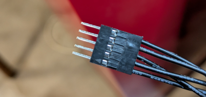
The pinout for the gauge and pin descriptions are shown below.
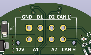
- 12V- Ignition power supply
- GND- Chassis ground
- CAN L- Can Bus Low(see pinout for your ecu)
- CAN H- Can Bus High(see pinout for your ecu)
- D2- This goes to one wire of the included switch. The other wire on the switch will go to a chassis ground. The switch is to cycle between the configurable preset screens.
- A1- Dimmer wire. This should get 12v whenever the lights are on. You can configure the bright and dim settings via wifi.
Installation Steps
This guide will go through the installation steps for the KaN gauge into a Miata gauge cluster.
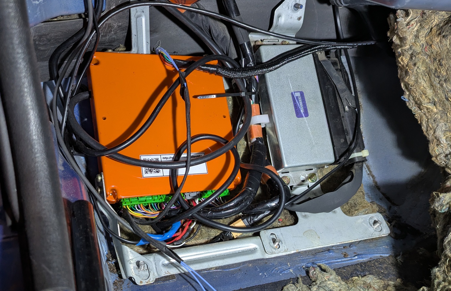
Locate your ECU
It will either be behind the seats, in the passenger foot well or under the steering wheel depending on the make, model and region of Miata.
Locate the CAN-H and CAN-L (CAN+ and CAN- respectively) pins on the ECU
For the different Miatas, the CAN lines are as follows:
- NA6: Pin 3D - CAN-H, pin 1F - CAN-L. NA6 Wiring Diagram
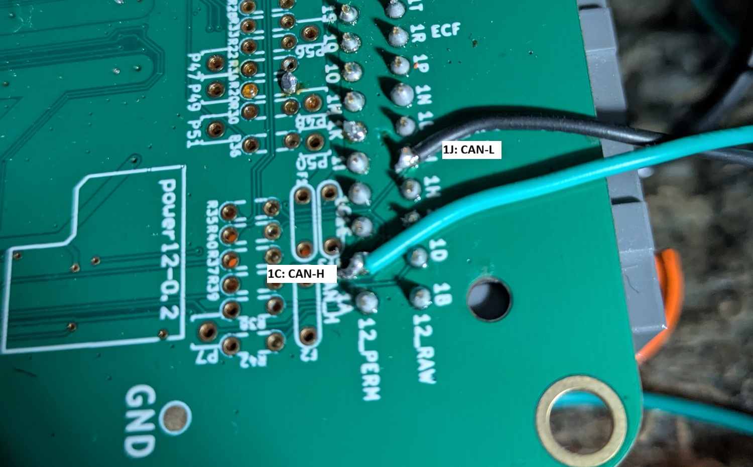
- NA8: Pin 1C - CAN-H, pin 1J - CAN-L. NA8 Wiring Diagram
- NB1: Pin 1C - CAN-H, pin 1J - CAN-L. NB1 Wiring Diagram
- NB2: Pin 3W - CAN-H, pin 3X - CAN-L. NB2 Wiring Diagram
Connect CAN wires to the canbus pins
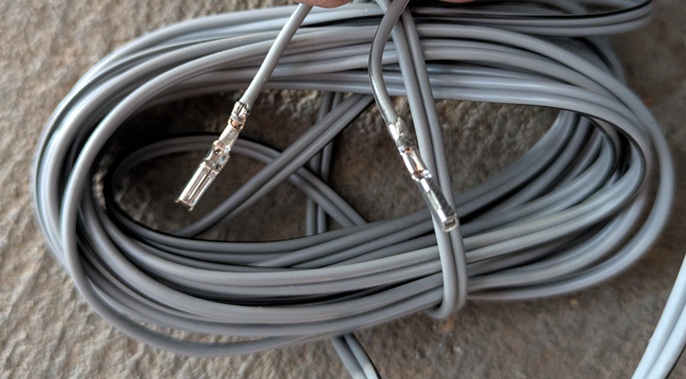
Measure several meters of wires (more than you think you'll need) and twist by constraining one end and putting the other end into a drill. Twisting is not necesary but recommended. To connect the wires to the ECU, there are two ways of doing this. The neatest is to crimp contacts onto the end of the wires and plug into the corresponding ECU wiring harness sockets (you can also re-use contact pigtails from a junk wiring harness). For NA's the contact part numbers are shown below. Be sure to note if you require the narrower or wider contacts for your ECU.
- .040" size TE brand contacts (175061-1)
- .070" size TE brand contacts (173631-6)
For the NB2, use the following contacts:
- 0.040" size TE brand contacts (1376700-1)
For NB1s the contacts are not the same as they use a JAE connector not TE as the other ECUs use. The JAE connectors plugs into the NB1 TE branded socket but the contacts in the JAE connectors are not the same. The JAE contacts are difficult to source and a 0.040" and 0.070" contact would be needed
For those with NB1s, no spare harness, or who don't want to wait in on contacts arriving in the mail; solder the CAN wires directly to the backside of the ECU to the corresponding CAN-H and CAN-L locations. Make sure to label which wire is CAN-H and CAN-L
Remove the dash
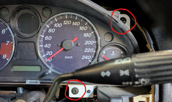
Remove the screws on the plastic on the underside of the steering column then unclip the top and bottom plastic halves around the indicators. Next lightly pull back on the plastic dash surround directly towards the steering wheel until it unclips. Be careful as it can be quite stuck and is known to crack. Next, unclip the three large plastic connectors on the back of the dash cluster. The four screws holding in the cluster can then be removed and the entire cluster should come free.
Route the CAN wires through the car to the gauge cluster
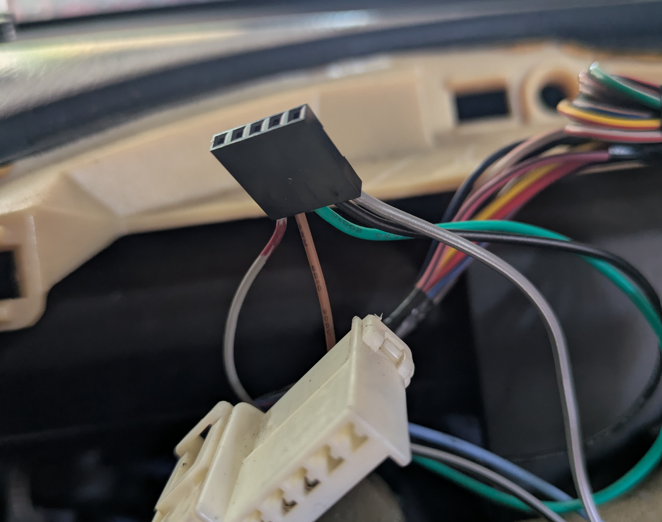
Use of a cable snake may help in the case you need to route the wires from the passenger footwell to the gauge cluster. In the image below, the wires have been routed through to the cluster but the wires have a 5 pin connector attached. This is to allow the two can wires, power wires and button to be disconnected from the car if the cluster needs to be removed in the future. There is nothing wrong with hardwiring all the connections if you plan on never modifying the wiring in the future.
Dissasemble the dash
Be careful with this as it is easy to break the tabs. Start by pushing each of the clear plastic tabs downwards until unclipped and gradually work your way around the dash doing this, each time push the tabs further out until the entire clear cover can be removed.

Next repeat with the black plastic tabs until the black cluster surround can be entirely removed.
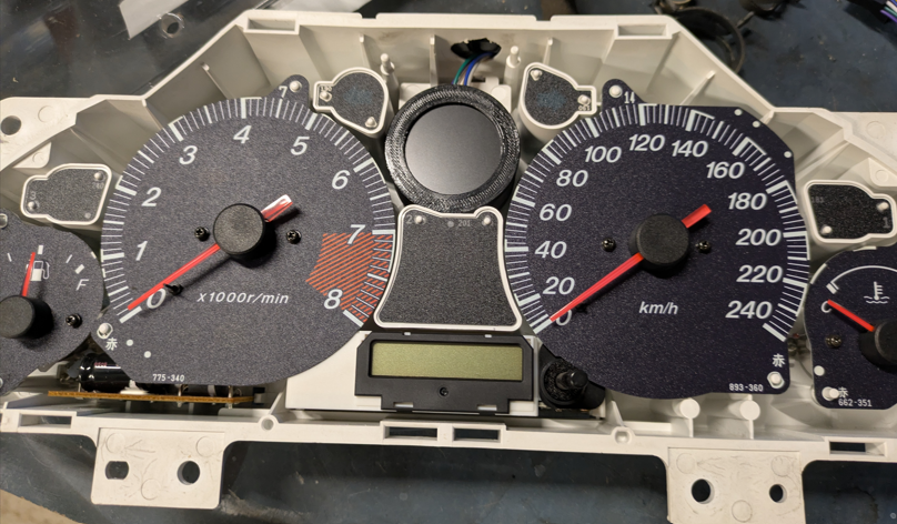
Unscrew gauge to be removed
The fuel, oil pressure and coolant temperature gauges all have three screws on the backside of the dash holding them in. Remove the screws from whichever of these gauges you want to remove in place of a KaN gauge.
Build gauge pod if necesary
If printing your own gauge pod such as this custom designed KaN Gauge Mount by Joshua Solanes, it may need to be assembled as per the steps in the provided link. Note that Josh's custom mount works for the oil pressure, coolant and oil pressure locations.
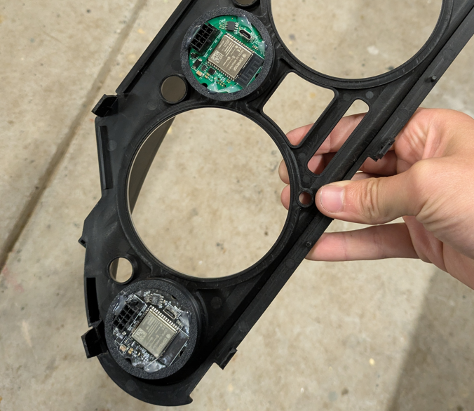
Install gauge(s) into the cluster
The gauges may either screw into the cluster like the oil pressure gauge does or they may press fit like Josh's gauge design. In the case of a press fit, power the gauge on before gluing it into place to ensure it is angled correctly so the text is horizontal. The image below shows Josh's gauges installed into the back of the dash.
Whichever way you do the wiring, make sure to label the wires or you'll forget which black wire is which.
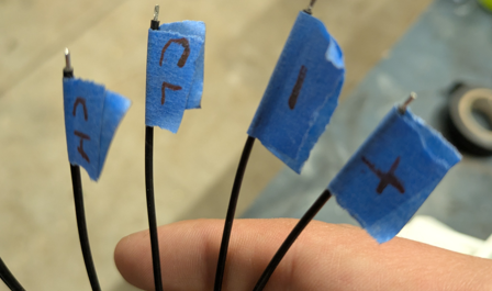
As an optional step, the wires which will not be soldered directly to the gauge cluster can have connectors added to allow for the cluster to more easily be removed from the car in the future.
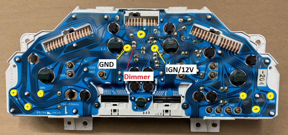
Wire up power
The simplest way to wire to power is to connect the power leads to the positive and negative pads on the back of the gauge that was removed to fit the KaN gauge. The wires can either be soldered directly to the pads or you can crimp ring terminals to them and screw the terminals onto the pads. In the image below, the left ring terminal is GND and the right is 12V. The third method is to source the power from the ignition fuze using a fuze pigtail from the fuzebox and a chassis grounding point. The wires from the gauge can be run either out the top of a hole drilled in the dash or through the unused screw holes as also shown below.
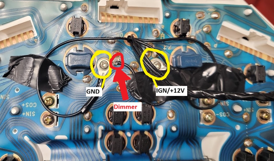
Wire up dimmer
The dimmer wire is connected to A1 on the PCB and will dim the gauge when connected to +12V. On the gauge cluster, the highlighted pad on the image above will be the easiest point to source the 12V dimmer signal from. The brightness level can be configured in the gauge settings.
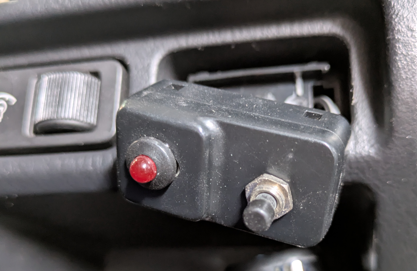
Wire up the screen select button
The button is wired to D2 on the gauge PCB and a chassis ground. It can be located anywhere on the car, but somewhere like next to the alarm light is nice and accesible
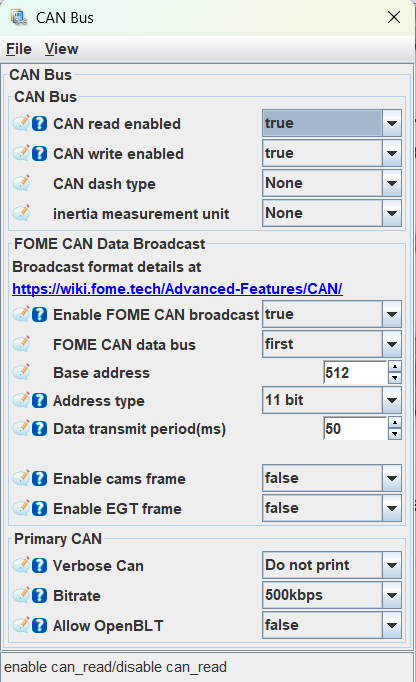
Configure CAN in Tuner Studio
Under the controller tab, set the CAN settings to match the image below.
Connect and test
Connect the gauge wires to the CANbus wires on the ECU and plug the cluster back in. Power the car on to test that the gauge works and receieves CAN data. If the gauge isn't working, the most likely culprits are:
- The wrong ECU pins are connected to the CAN lines.
- The CAN lines are backwards, make sure CAN-L goes to CAN-L and vice versa.
- The gauge wires are the wrong way around.
Finalise and re-assemble
Once everything is verified, carefully clip the gauge cluster back togethor and re-install into the car. Ensure any new wires are secured to the car so they will not vibrate and eventually break. Re-screw in the cluster and clip on the sun shade followed by the steering column plastics.
Gauge WIFI configuration
Through the KaN gauge web page, the interface can be configured to your desired specifications including gauge layout, displayed data, text & gauge colours, brightness, and warning thresholds. The gauge firmware is also updated through this page. When on the home page, the following options are displayed:
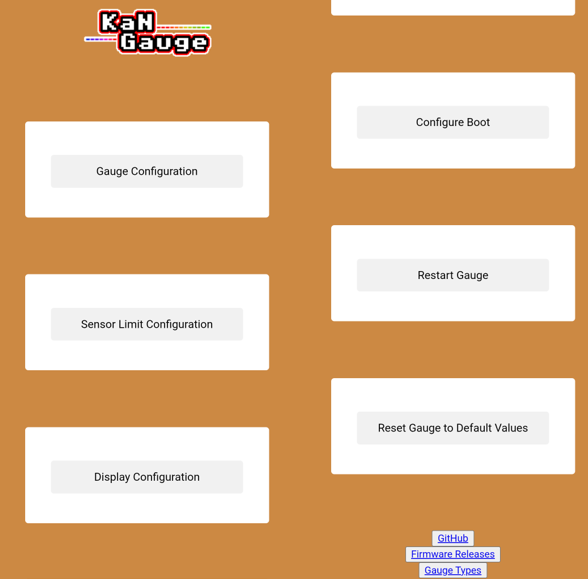
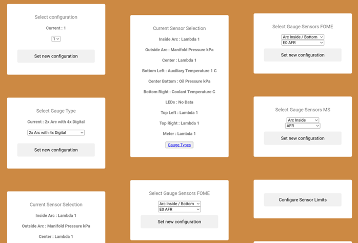
Gauge configuration
In the gauge configuration menu, the look and sensor selection can be configured. First select the desired configuration to modify (1, 2 or 3), these are the three gauge layout screens that can be cycled through using the button. Under that the gauge type can be selected. There are images of each possible gauge type on the KaN V2 Github here. Under that the current sensor selection displays which sensors have been selected for the chosen layout. For the sensor selection there are two "Select Gauge Sensors" boxes, only use the FOME one if using a FOME ECU and ditto for megasquirt (MS).
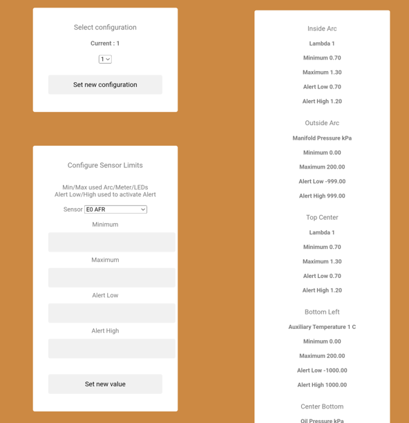
Sensor limit configuration
In the "Configure Sensor Limit" menu, the displayed sensor value range and alerts can be set. Ensure the correct configuration is set before configuring the sensor limits displayed in that configuration. Below the configuration will be a list detailing all current limits.
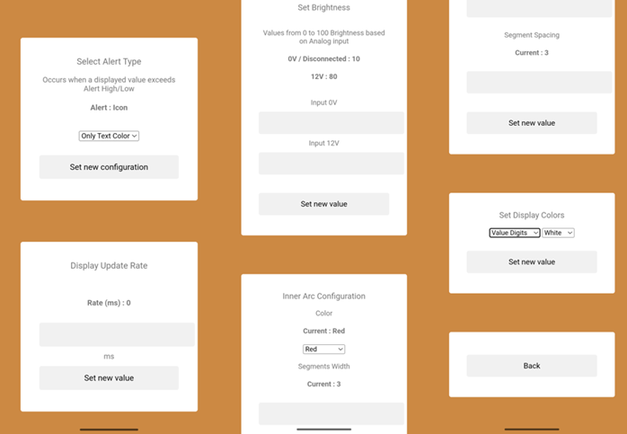
Display configuration
This menu allow for configuration of the alert types, display update rate, brightness, gauge ring colour configuration and other colour configuration. The selected alert type will trigger when any sensor exceeds its minimum or maximim alert ranges. For the display rate, this can be left at 0 or increased if you wish for a slower updating display. Below that the inner and outer arc colours can be set as well as the display colours where the value digits, unit text, alert digits and meeter needle can all be changed to a colour of your choice. The gauge brightness can also be configured in this menu to control the amount of dimming when the dimmer input A1 receives 12V.
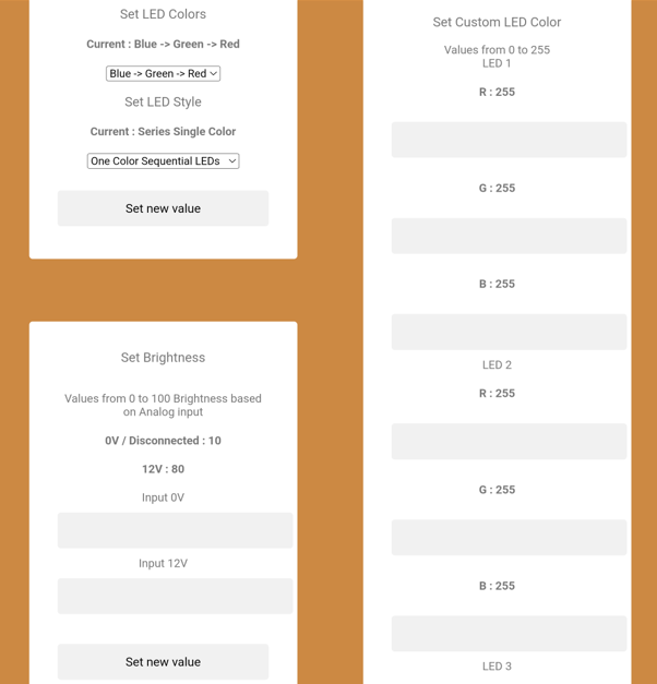
LED configuration
This menu allows for the LED colours and brightness to be configured. In the LED colours menu, they can be set to stay as a single colour or gradually change based on the sensor they are representing. Next the LED brightness can be configured like the screen brightness so it dims when the headlights are switched on. Lastly, custom LED colours can be set using the 0-255 RGB colour scale for each LED.
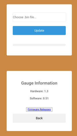
Update firmware
The gauge firmware can be updated from this screen. First, open the firmware releases link and download the latest gauge release ".bin" file. Then coming back to the gauge webpage, select the downloaded bin file and press update. When updating, make sure the gauge is powered from 12V when updating not the micro USB connector. In the rare case WIFI firmware updating fails, it can be manually updated over USB by following the flashing guide on Github.
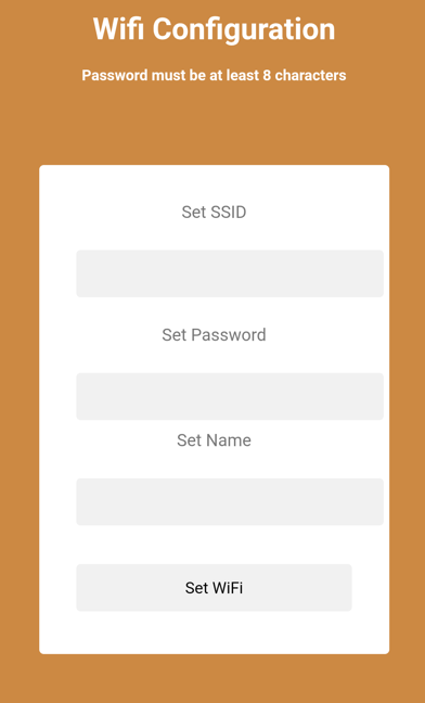
Configure WIFI
In this menu, the SSID, password and gauge network name can be configured. This is useful in the case that multiple gauges are installed and they need differentiation in the WIFI menu.
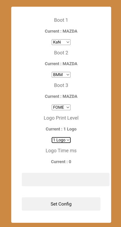
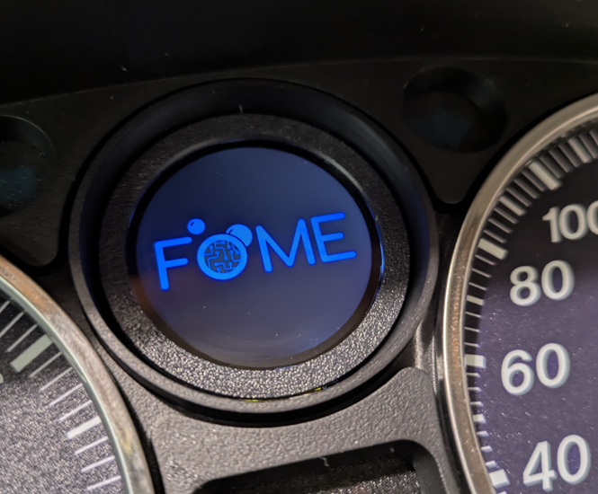
Configure boot
When the gauge boots, it can display up to 3 different logos. The order, logo time and logos displayed can all be configured in this menu.