Injector Configuration
This page describes the injection configuration settings and how to set up a set of injectors. Most FOME base maps are for the OEM injectors for that vehicle, e.g. a Miata base map is configured for the stock Miata injectors. Any modifications the the injectors will require the settings to be changed. Injector settings are crucial to be set up correctly for the rest of the tune to function correctly. It is highly recommended to flow test any new injectors before installing them, or at the very least finding their data sheet to work off of or data from another user who has them running. The closer the data in the configuration is to the actual injector performance, the better the results will be.
Injector Configuration Settings
Below is the Injection Configuration dialog box. The following sections will cover the settings in this menu.
Injection
Setting Enabled to true is generally a good place to start. The injection mode has 4 settings:
- Simultaneous: This fires all injectors at once and wastes quite a lot of fuel. It has some applications, but most modern EFI engines don't use it.
- Sequential: This fires one injector at a time which is what most engines will use. Make sure your firing order is set correctly under Base Engine > Base Engine Settings otherwise the engine may still run but will be spraying on closed valves which reduces atomization.
- Batch: This fires a set of injectors at once. On a 4-cylinder engine, this will fire one injector during one piston's intake stroke and another injector during another piston's exhaust stroke. At lower engine revs, batch injection does waste some fuel however at higher revs, both sequential and batch injection spray on closed valves as there simply isn't enough intake valve duration to spray the required amount of fuel.
- Single Point: Single point is used when one injector fuels all cylinders, similar to a single carburetor engine where one jet supplies fuel to all cylinders. In fact, single point is mostly used for converting older carburetted cars to EFI where the carburetor can be swapped for an EFI conversion kit.
Next up is Override VE/AFR Table Load Axis. For most EFI engines, set these to none as the axis defaults to MAP. The main time to change these to throttle position (TPS) is for a car with individual throttle bodies where a MAP sensor isn't fitted or is fitted but is giving inconsistent readings.
Injection Phase Control Mode controls whether the start, end, or center of an injector on/injecting-phase corresponds with the Injection Phase Table (to be discussed later). Most commonly, end of injection is used here; E.g. if the injection phase is 400 degrees (720 degrees in a complete 4 stroke combustion cycle), the injector will have finished spraying fuel at precisely 400 degrees.
Injection Settings
This is the first settings box to configure injectors where the flow rate and reference pressure will be input.
Injector flow is the characteristic flow rate of the injectors. The flow units can be changed to grams per second (g/s) through setting Injector flow units to mass flow, and to cubic centimeters per minute (cc/min) by setting volumetric flow. If you are using injector small pulse correction (to be discussed later), this value will need to be in g/s which requires converting cc/min to g/s. To do this conversion you take the rated injector cc/min, divide it by the specific density of fuel (0.72 to 0.77), then divide it by 60 seconds. e.g. 400(cc/min)/0.72 = 555 g/min, 555(g/min)/60 = 9.26g/s.
Injector flow compensation mode is for configuring the type of fuel pressure system. None = I have a MAP-referenced fuel pressure regulator. Fixed rail pressure = I have an atmosphere-referenced fuel pressure regulator (returnless typically). Sensed rail pressure = I have a fuel pressure sensor.
Injector reference pressure(kPa) is the pressure at which your injector flow is known and should be stated on the product page or datasheet. For example if your injectors flow 400cc/min at 3.5 bar, enter 350kpa here. In the case of a fixed rail pressure compensation mode, this number also needs to be the fuel rail pressure for the specific vehicle.
Fuel Characteristics
This box is where the air to fuel stoichiometric ratios are set. Stoichiometric ratio (:1) is the stoichiometric ratio for your primary fuel. When Flex Fuel is enabled, this value is used when the Flex Fuel sensor indicates E0 (no ethanol/pump gas). E0 (pump gas) = 14.7 E10 = 14.1 E85 = 9.9 E100 = 9.0. Below is E100 stoichiometric ratio(:1) which should be 9 by default. This box will become active when Flex fuel sensor is set to an input in the Sensors > Other Sensor Inputs menu.
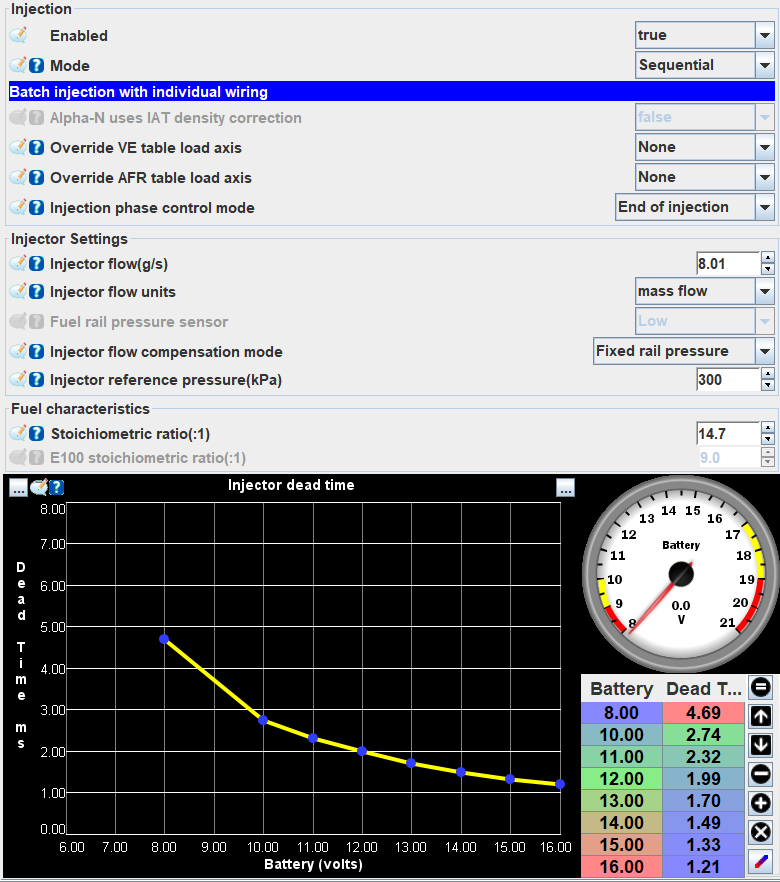
Injector Dead Time
The injector dead time is basically the delay the injector takes when sent a pulse before it starts spraying fuel. Getting this right is essential for having a car that runs well. Ideally the dead times will be included in the data-sheet for injectors or searchable on forums. Dead times are dependant on the battery voltage and fuel pressure. E.g. Bosch EV14 370cc/min injectors with 300kPa fixed fuel pressure will need the dead times for the range of possible battery voltages (as higher voltages activates the injectors quicker). A good flow testing shop should be able to provide this data for your injectors. If you have your own flow testing setup, the injector testing page details how to determine the dead times.
To roughly tune the dead times without a flow testing setup, get the engine to a stable idle and check the VE value needed to get stoichiometric AFR. The VE value requires should roughly correspond to the table values below. If the VE is above, the dead time is too low and needs to be increased as not enough fuel is spraying. If the VE is below, decrease the dead time as too much fuel is being sprayed. This only needs to be done at idle as the dead time is a high percentage of the injector duty cycle pulse length at idle but at high RPM it only makes up a small duration. If the dead times need to be increased slightly from the manufacturer data, that is ok as the ECU has it's own processing delay which stacks on top of the physical dead time and also needs to be factored in.
| Idle Engine kPa | VE |
|---|---|
| 90 | 25 |
| 80 | 30 |
| 70 | 35 |
| 60 | 40 |
| 50 | 45 |
| 40 | 50 |
| 30 | 55 |
| 20 | 60 |
Injector Test
This dialog allows you to test injectors are working. Ensure the fuel pump is off if you just want to hear them click to verify correct cylinder position or wiring (or fuel may go everywhere or flood the cylinder). See the injector testing page for more information.
Cylinder Bank Selection and Cylinder Fuel Trims
Cylinder bank selection allows is an advanced setting and allows for each cylinder to be assigned a number corresponding to which cylinder fuel trim table it will use. For cars with one WBO2 sensor, leave all banks at 1. For cars with multiple WBO2 sensors, group cylinders with the same WBO2 sensor in the same bank. In the cylinder fuel trims, the Fuel trim cyl 1 table trims all cylinders with bank 1 set, Fuel trim cyl 2 with bank 2 set and so on. The trim table values are in percent of fuel to add or take away E.g. if cylinder bank 2 runs 5% leaner than bank 1, add 5% trim.
Injector Small Pulse Correction
This settings menu compensates for a non-linear injector flow rate. Smaller injectors have an approximately linear relationship between fuel injector flow and duty cycle however larger injectors typically do not and follow more of a logarithmic growth curve which is where the Small pulse correction mode comes into play. For small injectors or novice users, this can be set to none. Larger injectors will work perfectly well with the mode set to none, the VE table will just need to be tuned to compensate.
For advanced users with Ford or Bosch injectors such as the Bosch EV14s/Ford MU52 (the MU52's are re-branded Bosch), set the mode to Ford (dual slope). This mode approximates logarithmic growth using two pulse slopes in g/s; the small pulse (or ALOSL for low RPM) and the large pulse slope (AHISL for higher RPM). At low RPM the small pulse slope injector flow rate is used up until the small pulse breakpoint (FUEL_BKT in mg) is reached, then the large pulse slope is used. The MU52 transfer function documentation is a good place to start for these values, Just note that the values will need to be converted from lb and lb/s to grams and g/s. The ALOSL, AHISL and FUEL_BKT will need to be multiplied using the corresponding tables depending on your target fuel pressure (these tables also need to be converted from PSI to kPa).
For even more advanced users, the mode can be set to polynomial where the correction can be configured to exactly match the injector flow rates.
Staged Injection
Staged injection is an advanced feature allowing for a second set of injectors to be used. For example instead of a single 1000cc/min injector per cylinder, using two 500cc/min injectors per cylinder. The injector flow and dead times are set as they are for regular injection setups. The main difference is the Staged injection % table which blends the fuel delivery from the first and second set of injectors. For example in a large turbo setup, if the primary injectors at full load begin to reach their maximum around 5000RPM, the second injector set can have their injection % set to ramp up as the vehicle reaches 5000RPM to ensure that there is adequate fuel delivery.
Injection Phase
Injection phase is the angle which fuel is injected within a combustion cycle. The injection phase angle will commonly be set between 380-440 degrees for the whole RPM/load table. This is because 4 stroke engine completes two 360 degree rotations in a full combustion cycle consisting of the power stroke from 0-180 degrees, exhaust stroke from 180-360 degrees, intake stroke from 360-540 degrees, and compression stroke from 540-720 degrees.
Ideally the injection phase is configured such that the injection has finished before the intake valves have closed. At low RPM, this is a lot easier to achieve as the injection duration is very short and can be timed earlier in the intake angle range. At high RPM, it is ideal to finish the injection as close to the maximum intake valve opening angle as possible to get as much fuel into the cylinder as possible. If your vehicle intake cam profile is known, you can better configure the injection phase at high RPM to complete near the maximum cam lift angle occurs in the intake phase.
Tuning the injection phase is difficult and can have some gains however it is not strictly necessary and leaving it at the base map value in the 380-440 degree range is perfectly fine. If you do want to tune it, vary the phase it until the AFR goes lean then continue moving the phase in that direction until the degree of leaning reaches a maximum, that will be the peak injection phase angle for the specific RPM/load being tuned for. If the AFR goes rich, vary the phase the other direction. For well known platforms such as Miatas, many community members have extensively developed injection phase angle tables which can be duplicated given you are running a similar setup to them (same engine, cams, injectors, fuel rail, etc.).