Charge Temperature Estimation
Charge temperature estimation is used to model the increase in intake air temperature after the IAT sensor by the heat of the intake piping, intake manifold, cylinder head, etc. Without accurate charge temperature estimation it is possible that an engine may exhibit leaner air fuel ratios at higher IATs, especially under low load like idle and light cruise. This is common when the VE table is tuned at lower IATs without charge temperature estimation.
Mode
Three modes of charge temperature estimation are available; RPM+TPS, Air Mass Interpolation and Table.
RPM+TPS (Default)
Interpolates between four coefficients based on RPM and TPS to generate a coefficient for estimating the intake air temperature. The coefficient determines the percentage of the estimated air temperature that comes from the IAT with the remainder coming from the CLT.

For example, a coefficient of 0.2500 means that 25% of the estimated air temperature is from the IAT, and 75% from the CLT. If the IAT was 40C and the CLT was 80C, the calculation for estimated air temperature would be (40C * 0.25) + (80C * 0.75) = 70C.
A coefficient of 0.9000 (which may be used at high loads/RPM) would result in the calculation (40C * 0.90) + (80C * 0.10) = 44C. A coefficient of 1 means that the charge temperature estimate would be the same as IAT.
Air Mass Interpolation
Also labeled as Airflow interpolation mode. This uses linear interpolation between the low flow coefficient at zero flow and the high flow coefficient at the max air flow to calculate the balance between IAT and CLT to arrive at the final estimated air temperature. Similar to RPM+TPS, the calculated coefficient determines what percentage of the IAT makes up the charge temperature estimate.
For example, a low flow coefficient of 0.100, a high flow coefficent of 0.900 and a max air flow of 300 kg/h would result in a calculated coefficient of 0.5 at an air flow of 150 kg/h. This means that the charge temperature estimate would be a 50/50 split between IAT and CLT. At or above max air flow, the calculated coefficient would be 0.9. Similar to the above examples in RPM+TPS mode (40C IAT and 80C CLT), the resultant charge temperature estimate would be (40C * 0.90) + (80C * 0.10) = 44C at or above max air flow.
Table
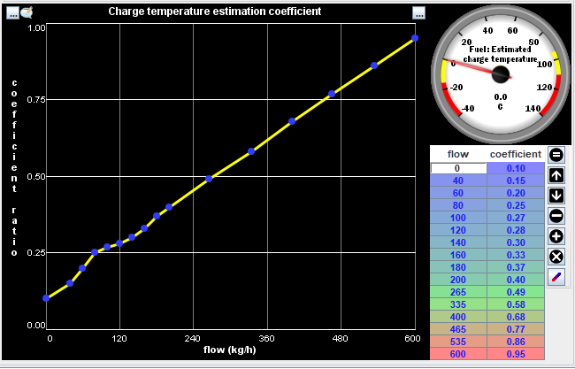
Uses a 2D table to return the charge temperature estimation coefficient based on the calculated flow rate. Similar to the above examples, the resultant charge temperature estimate is calculated by (IAT * coefficient) + (CLT * [1 - coefficient]).

Increase rate limit, Decrease rate limit
These settings control how quickly the charge temperature estimate value can increase or decrease to the new calculated value. The unit is degrees Celsius/second (degC/sec). Refer to the output Air: Charge temperature estimate. Note that there are two outputs with this name, one in degC and the other in degK.
For example, if the current charge temperature estimate value is 40C and the modeled charge temperature should be 50C, an increase rate limit of 1 deg/sec means that it would take 10 seconds for the charge temperature estimate value to increase from 40C to 50C.
Conversely, if the current charge temperature estimate is 50C and the modeled charge temperature changed back to 40C, a decrease rate limit of 5 deg/sec means that it would take 2 seconds for the charge temperature estimate value to decrease from 50C to 40C.